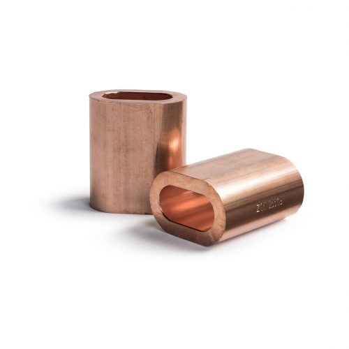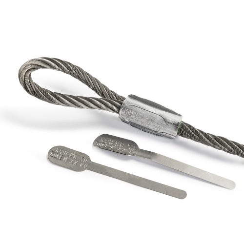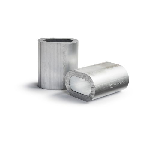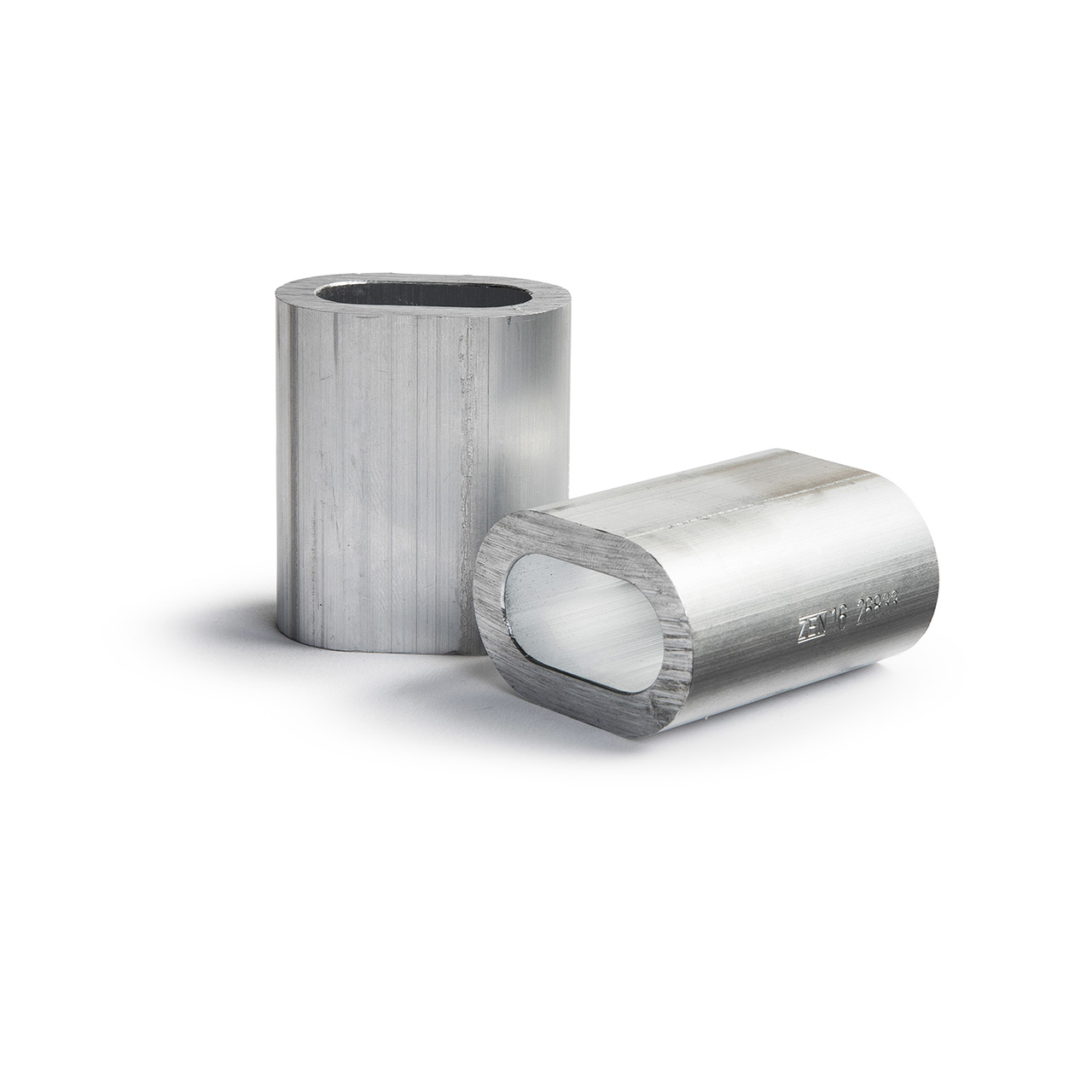
ZEN® 13411-3 Ferrules
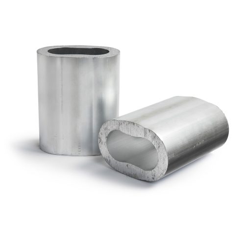
Aluminium ferrules compliant with DIN EN 13411-3 for rope slings compliant with DIN EN 13414-1.
- For wire ropes with a max. tensile strength of 1,960 N/mm2
- Suitable for steel wire ropes compliant with EN 12385-4
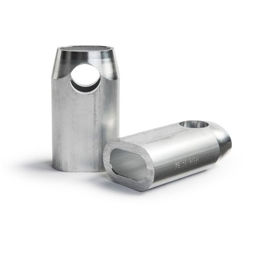
- Manufactured from seamless tubes according to DIN EN 13411-3
- Available in the sizes 2.5 – 60
- Available in the sizes 1.0 – 2.0 outside of the standard
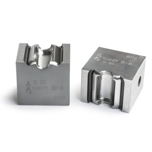
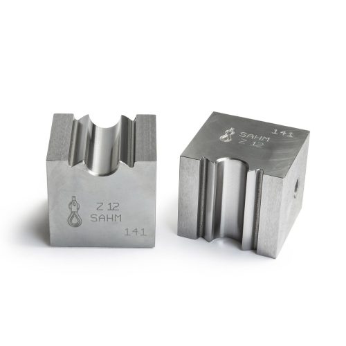
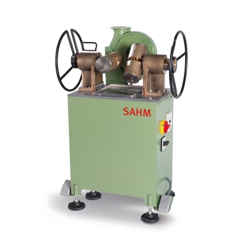
- Finished with our Swaging dies “Cylindrical” with cutting edges (Form A) or Swaging dies “Rounded” (Form B)